|
Constructing a Fully Integrated and Automated Capillary HPLC From a Standard High Flow HPLC
|
||||
|
Peak retention time reproducibility, high throughput, and overall work efficiency all rely on automation. If the standard HPLC you are using for the conversion has an autosampler then it may be possible to take the simple heart of the conversion, see Figure 1. and integrate it into the existing HPLC see Figure 3. The best way to proceed is to just give it a try. The figure and text below describe the conversion. |
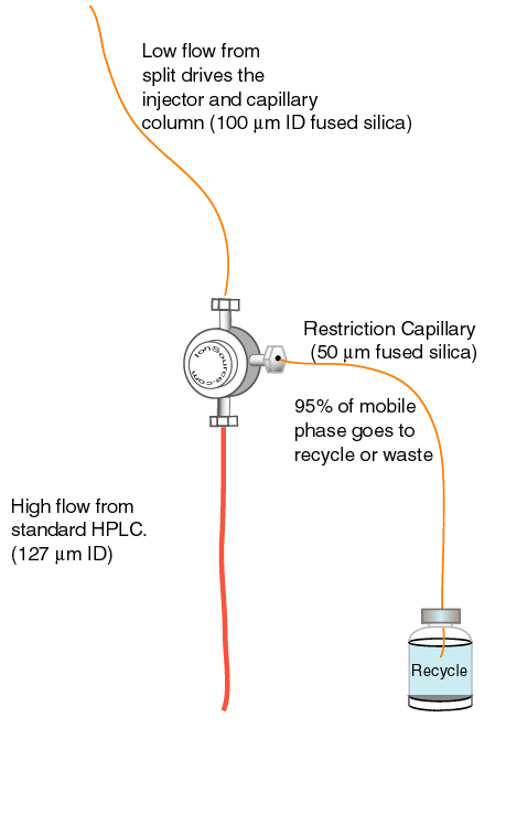 Figure 1 |
|||
|
|
Schematic of an HP 1090 conversion.
|
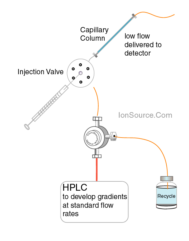 Figure 2 |
||
|
|
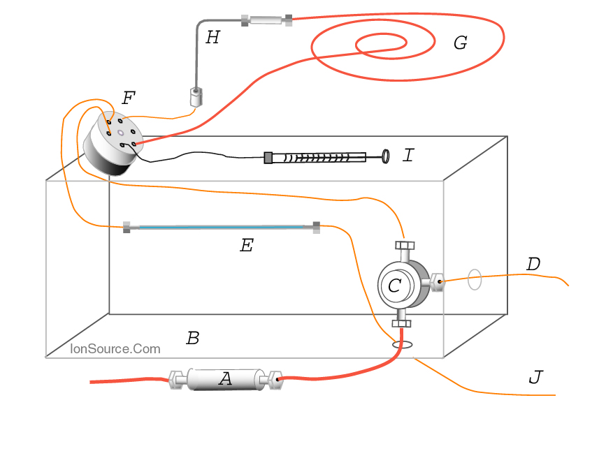
Figure 3: A is the static mixer. B is the heated column compartment. C is the splitting tee. D is the restriction capillary, "resistor", 50 µm ID, 50 cm length. E is a 320 µm ID capillary HPLC column. F is the HPLC switching valve which moves the loop into the flow path for injection and moves the loop out of the flow path to draw sample into the loop via... H the autosampler injection needle. G is the reduced volume loop (10 to 20 µL) made from 127 µm ID PEEK™ tubing. |
 |
||
| Figure 3 | ||||
|
We have discussed that the tee is placed after the HPLC's dynamic or static mixer to allow for the HPLC to pump and mix solvents at normal flow rates. This simple placement of the tee close to the injector eliminates delay volume and puts the capillary chromatogram on the same time scale as a comparable standard chromatogram. In the automated capillary setup the reduced flow rate is asked to drive a larger part of the HPLC system, therefore, care must be taken to address areas that may contribute unnecessary dead volume. In this conversion the flow after the tee is directed toward the HPLC's internal switching valve, see Figure 3. This valve switches flow to and away from the loop and autosampler needle. When the system is making an injection, flow from the pump is directed away from the injection needle and sample loop as the syringe draws sample out of the injection vial. In the HP1090 HPLC after the system is finished drawing sample the needle reseats and once again becomes part of the flow path along with the sample loop. When the valve switches, the sample in the loop is loaded onto the capillary column. One potential source of dead volume is the sample loop. Most HPLCs are equipped with a large diameter 250 µl sample loop. At 5 µl/min. it would take a minimum of 50 min. for the solvent to be completely exchanged in this loop. The simple solution is to make a 10 to 20 µL loop from 100 µM ID tubing. See our tutorial on loop construction and system volume calculation. A 10 µL loop with a small ID will only take 2 to 3 minutes to completely evacuate. The next issue to address is the volume of the systems switching valve. This issue is more difficult to address. Most valve manufacturers make low dead volume switching valves. If your switching valve has an unusually large internal volume it may be possible to fit it with a rotor that has smaller channels, check with the valve manufacture. In the case of the series I HP1090 the valve functions well at a 1-5 µL flow rate. Next the flow is directed from the valve to the capillary column. Find the port out of the switching valve that normally directs flow to the column and replace it with 50 µM ID fsc. At this point if your HPLC has column temperature control capability you can control for retention time variability by placing the capillary column in the heated column compartment. If your HPLC system does not have column temperature control capabilities, column heating jackets are commercially available. Heat transfer is very efficient for most capillary designs since the column diameters are small. Column temperature control is not mandatory but as with standard columns it will help with peak retention time reproducibility and will add another dimension of chromatographic control. The tee could potentially be another source of temperature induced variation. The heated column compartment can be conveniently used to control the temperature of the tee, see Figure 3. Once the capillary HPLC is established one must be concerned with UV detection. Standard HPLC flow cells have internal volumes that are too large for the low flow rates of capillary columns. Conventional HPLC UV flow cells have internal volumes as large as 12 µL. For capillary UV detection a capillary flow cell must be purchased or constructed. Refer to the chapter on capillary UV detection. |
|
|||
|
. |
||||
|
TOC Introduction Glossary Simple System Automation UV Detection Plumbing The Truth About Splitting Applications Order Components References |
 |
|||
| - | ||||
|
home
| disclaimer |
||||
