|
|
Click on the thumb nails in this column for a larger view | ||
|
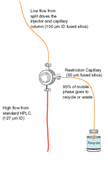
Flow rate reduction is the primary principle behind the HPLC conversion. Flow rate reduction is accomplished using a flow splitting tee, see Figure 1. Flow is brought in from the HPLC pumps at a standard flow rate (200 µL/min) through the mixer and then split at the tee. The majority of the flow (~195 µL/min) is split to waste, the remainder is used to drive a capillary HPLC column at 1-8 µL/min depending on the ID of column. If the analysis uses an isocratic HPLC method the waste flow can be easily recycled to conserve mobile phase and reduce waste costs. Remember the flow is split immediately after the pump leaving the majority of the mobile phase untouched and ready to be recycled. |
 Figure 1 |
||
|
|
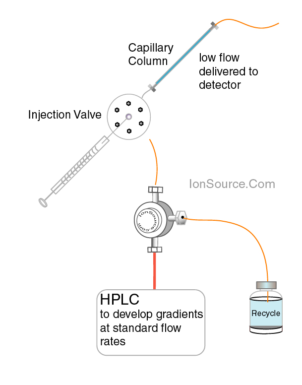 Figure 2 |
||
|
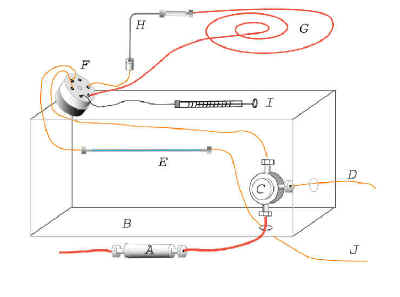
Figure 1: Mobile phase is brought in from the HPLC pump at standard flow rates through the red tube to the tee. The majority of the flow is split out through the restriction capillary, pictured to the right of the tee. The remaining flow is used to drive an injector which is used to load sample onto a capillary HPLC column, this set up is described below and in Figure 2.. |
|||
|
An HPLC injection valve is placed in-line between the tee and the column for sample introduction, see Figure 2. The flow through the column is changed by adjusting the length of the restriction capillary or by varying the flow rate from the HPLC slightly. After constructing the simple capillary HPLC system the flow rate can initially be adjusted by starting out with a low flow rate (~100 µL/min) and then measuring the output through the column and monitoring system pressure. The flow rate can be measured by collecting the column effluent into a small tube then using a hand held pipettor or syringe to measure the volume. System pressures seldom exceed 200 bar, at a presplit flow rate of 200 µL/min the system pressure is somewhere between 100 and 150 bar for a standard 0.32X250mm column. However the system pressure may be higher depending on the column packing and particle size. With columns that are packed with a smaller particle, (3 micron), it may be necessary to increase the system flow and thus the overall system pressure to get the desired flow out of the capillary column (4-8 µL/min). |
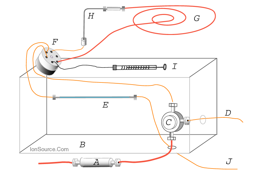 Figure 3 |
||
|
|
||
|
Figure 2: The figure above shows the flow splitting tee described in Figure one driving a sample injector. Samples are loaded into the injector loop and then are manually injected onto the capillary column. A capillary UV detector or mass spectrometer or both can be used to detect analytes. |
|||
|
Flow out of the capillary column can also be adjusted by lengthening the restriction capillary coming out of the flow reducing tee. Another method used to increase the flow rate out of the capillary column is by decreasing the internal diameter of the restriction capillary. The two procedures just mentioned increase flow resistance at the tee and force more liquid through the capillary column, however it is simpler for most chromatographers to just adjust the overall system flow rate. To measure the flow rate collect the effluent into a small container and measure the volume after five minutes using a micro hand held pipetter or syringe. Adjust the flow rate up accordingly. We usually target 4 to 8 µl /min as the flow rate for a 320 micron ID capillary HPLC column. The system pressure can be monitored via the HPLC. As stated previously, common pressures needed to drive a 0.32X250mm, 5 micron packed capillary column at 5 µL/min are ~ 100 bar. With this set up samples can be injected manually. The tee is placed close to the injector, thus minimizing system dead volume. The HPLC is allowed to develop gradients and mix solvents at it's standard flow rate before the tee thus eliminating delay volumes. Good luck. You will need to consider how to detect the peaks coming from your new capillary HPLC, and also keep in mind that the ultimate in reproducibility will always be obtained through automation. For pointers on detection and automation see the appropriate chapters. |
|
||
|
. |
|||
|
TOC Introduction Glossary Simple System Automation UV Detection Plumbing The Truth About Splitting Applications Order Components References |
 |
||
| - | |||
|
home
| disclaimer |
|||