|
Fluidics |
Click on the thumb nails in this column for a larger view |
|
As evidence against using a flow splitter it is often heard that the ratio of the split changes with the changing viscosity of the mobile phase during the HPLC derived organic gradient. One might imagine that this would mean that the flow rate through the column would decrease with decreasing viscosity as the fluid would be less likely to be pushed through the high pressure (column) arm of the split. But this really does not make any sense because as the viscosity changes the mobile phase also meets lower resistance through the column and thus the split ratio remains the same. The physical data in the graph below demonstrates this principle.
Figure 6 above demonstrates that as the viscosity changes over the organic gradient as evidenced by the decreasing system pressure, red line, the flow measured through the capillary column remains stable, pink line. Note that the system pressure decreases nearly 30% from 70 to 50 bar. This experiment demonstrates that the changing viscosity does not affect the split ratio greatly. The only thing that can change the ratio is a change in resistance through either arm of the splitter. A reality is that changing organic content could cause the stationary phase to swell or shrink thus changing the resistance on the column are of the split effectively changing the split ratio. This does not seem to be the case in the experimental data shown above. Flow rate changes may be amplified at lower flow rates. One last nugget. One might expect that you would need to change the configuration of the splitter when changing to a column of a different diameter. This only seems to make sense. Our experience has been that columns are rather self regulating, within reason. Larger diameter columns let more mobile phase through and smaller columns let less mobile phase through as would be the demand. For example the standard splitter used for running 320 µm ID columns uses a 50 µm ID X 50 cm resistor with a pre-split flow rate of about 200 µL/min.. We have found that when changing to 500 µm ID columns we can use the same resistor and merely start out at a lower flow rate and adjust up until a suitable flow rate is achieved, often the pre-split flow rate is not much different. To choose a suitable flow rate for a column of given diameter visit the linear velocity page. Take note that columns can be run at lower and faster than recommended flow rates and that the chromatographic and scientific goal should dictate the exact flow rate through the column. |
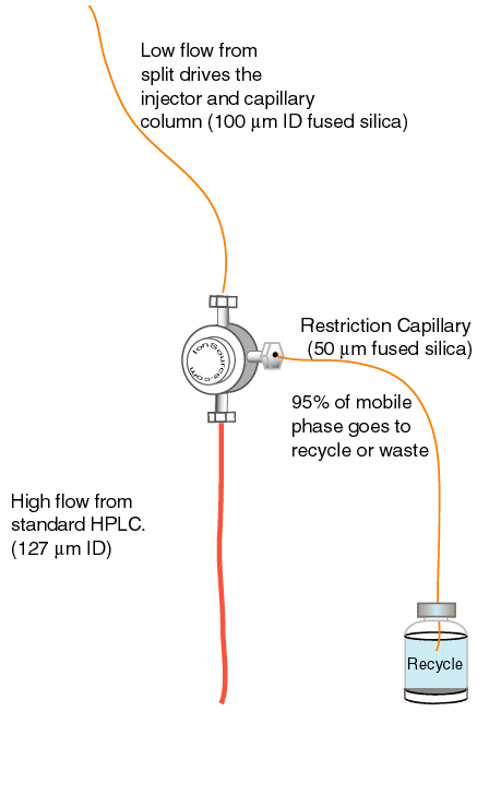 Figure 1 |
 Figure 2
|
|
Figure 3
|
|
|
. |
|
|
TOC Introduction Glossary Simple System Automation UV Detection Plumbing The Truth About Splitting Applications Order Components References |

|
| - | |
|
home
| disclaimer |
|